It is alive!
03 Jan 2026It is alive!
The 8-bit computer works! Well– in any case: some parts of it do.
The program that Ben uses in his videos works! It outputs 42 (as it should)
0:  LDA [14]
1:  ADD [15]
2:  OUT
3:  HLT
14: #28
15: #14
That means that the commands: LDA, ADD, OUT, HLT are implemented correctly!
In addition to my previous lessons-learned, here are some more insights:
-
Build using the schematics. Using the videos is fine as reference, but they should not lead.
-
Redraw the schematics if you make changes to the circuits. For example, you want to do this if you switch out components. I used KiCad.
-
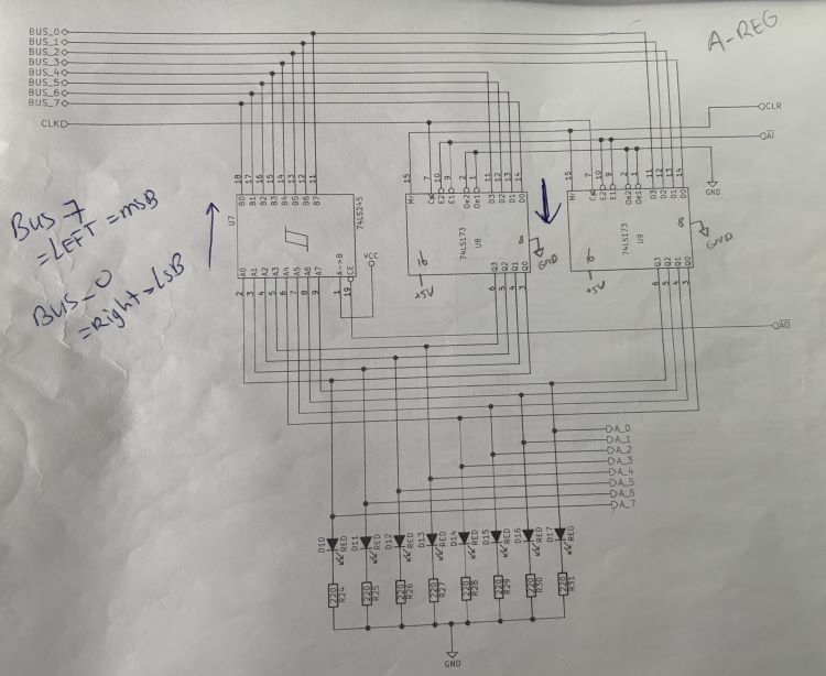
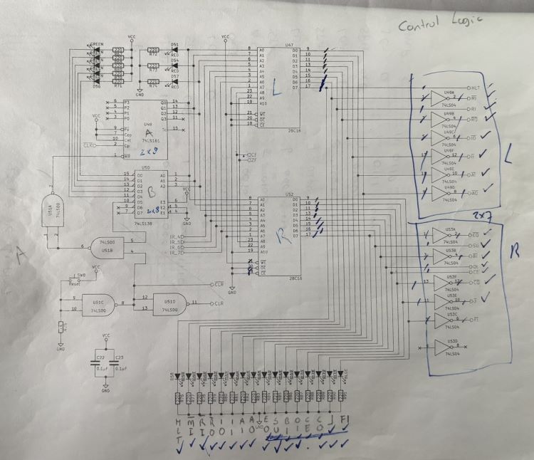
Don’t be afraid to mark up schematics. I marked them quite a bit. Sometimes with ‘L’ and ‘R’ to denote components (left or right), or with arrows to denote direction of data flow. It helps understand what’s actually going on, which is necessary to troubleshoot.
For example:
-
Pull all unused inputs high or low so that the corresponding output is high. I used 10k resistors.
-
Pull all outputs on the microcode EEPROMs high or low. Active low control signals get pulled high; active high control signals get pulled low. I used 10k resistors.
-
Add current-limiting resistors to all LEDs. I forgot the program counter ones, which caused their 74LS245 to not behave nicely. This does mean that you’ll have to move stuff around on the board; there simply isn’t enough space to put LEDs with the current-limiting resistors to keep them where Ben has them in his videos.

-
Don’t skip any wires ;) It took quite a bit of troubleshooting to realize that I never connected the 74LS283s in the ALU to the A-register. Oops.
-
When you get to the stage that you have all of the boards in use, hot-glue them to a piece of 1/8” plywood. That allows you to move your project without worrying that things are going to shift. I made mine to be the height of the computer, but gave myself about 10” in either side (left, right) so I can move my pliers, multimeter, etc. with the project.
What’s next?
Write code to test all the instructions! I’ll post updates about that too.